“From concept to implementation” – this simple but powerful statement precisely summarizes what an experienced rapid tooling service does on a daily basis, providing a variety of services for the production of vacuum casting.
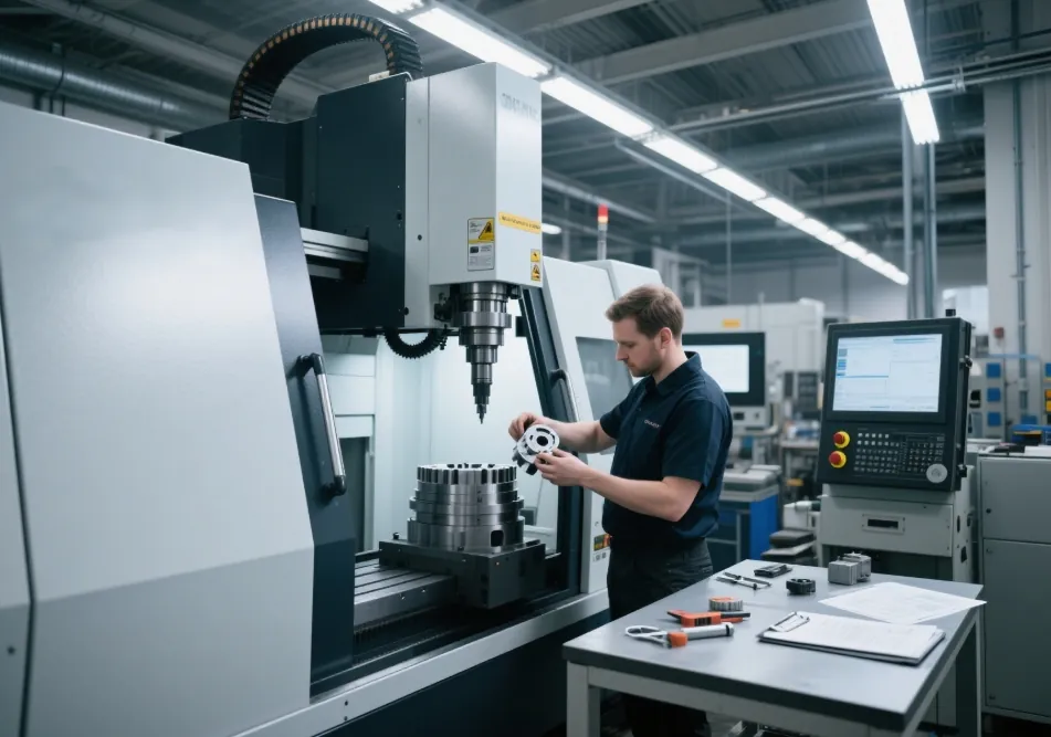
Every manufacturing process, even foundry production, begins with development. First designers use cutting-edge CAD 3D technologies to create parts and products of any complexity in the shortest amount of time.
Not only drawings in accordance with requirements, but also mathematical 3D models, natural models, or even a simple sketch on a sheet of paper, can be used as technical tasks for building.
The best companies use 3D scanning equipment, which allows you not only to obtain an identical copy of the goods but also to confirm the compliance of the obtained product with the original.
The usage of CAD programs greatly lowers design time and enhances the quality of design work performed, which has a beneficial effect on the finished product’s quality.
To get a product with the appropriate performance qualities, you don’t have to delve into the nuances of fabrication and understand the properties of metals or plastics. Service’s rapid tooling engineers thoroughly examine your product using professional systems and recommend the optimum alloy brand and casting procedure for you.
Table of Contents
ToggleBefore beginning to build the model for casting, the engineer must first resolve any technical issues:
- Selection of casting method and casting kinds;
- Adaptation of the original design to the chosen technology and the equipment’s capabilities;
- Calculation of machining allowances, assessment of the degree of accuracy, and casting dimension tolerances;
- Approval of the final casting parameters, taking into account the material’s flow characteristics and shrinkage;
A parametric computer model of the casting is built using contemporary CAD programs. It is the primary basis upon which equipment construction begins.
Next is the process of determining:
- The primary mold surfaces;
- The connecting surfaces required for aligning and assembling the various pieces into a whole;
- Auxiliary channels and elements are utilized in technology for cooling and heating, melt supply, and casting deformation compensation;
- Fastener holes and slots;
The final stage of design is the distribution of documentation, which is a collection of drawings for all parts and assemblies.
Primary categories of materials and their properties are used in rapid tooling.
Model tooling can be made from a variety of construction materials. The most significant requirements are strength, surface wear resistance, a specific degree of heat conductivity, and processing deformability.
The most frequently used are:
- Tool steels and alloy steels are used to make molds and machine parts.
- Carbon steels, aluminum alloys, and cast irons – for mass and high-volume casting models in casing molds;
- Aluminum and alloys based on it – for molds that work under periodic heating; plywood, wood, and MDF – for models, entrances, and bar boxes for single and small castings, as well as large-scale products;
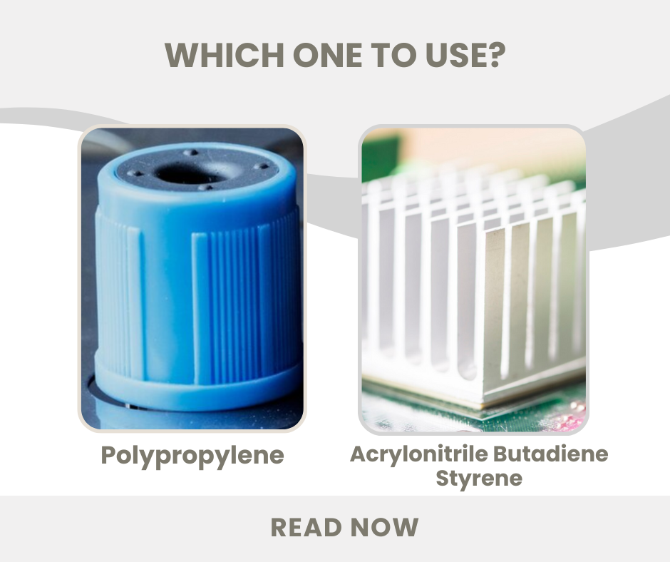
- plastic, for models with a complex configuration.
The material is chosen based on usage (the number of molds or castings) without compromising the accuracy of the surface geometry.