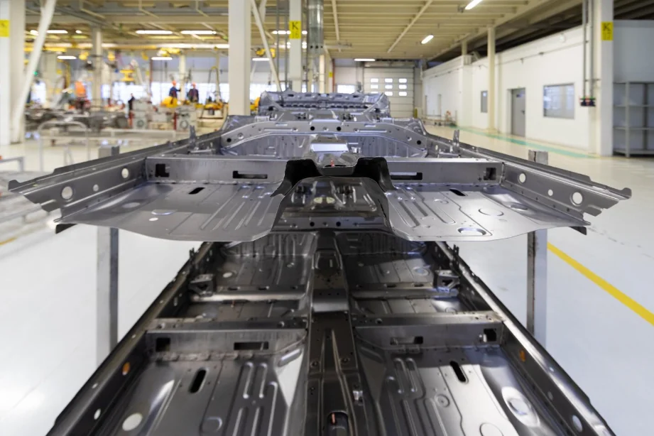
In the world of precision manufacturing, the difference between a high-performance component and a scrapped piece of metal often comes down to fractions of a millimeter. At APT, we frequently see designs where the transition from roughing to finishing is misunderstood, leading to either wasteful processing times or parts that cannot meet final geometric tolerances.
The critical variable in this equation is machining allowance.
Whether you are designing complex aerospace components or high-volume injection molds, understanding how to calculate and specify the correct stock allowance is essential. This guide explores the technical necessity of machining allowance, the variables that influence it, and provides a standard machining allowance chart to streamline your engineering communication.
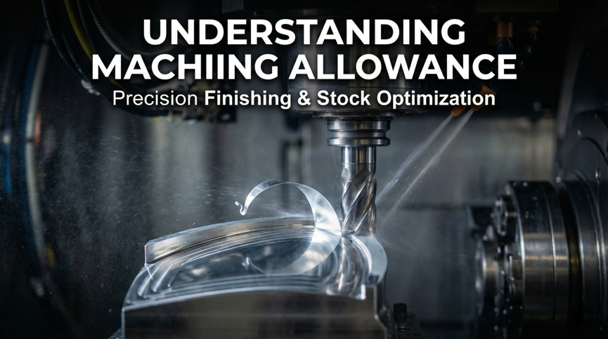
What is Machining Allowance? (And Why It Is Not “Tolerance”)
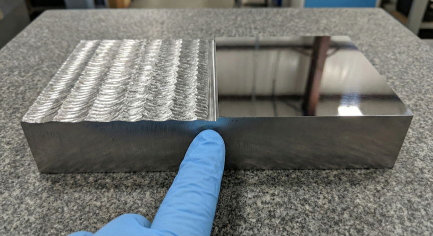
Machining allowance (also known as stock allowance or finishing allowance) is the layer of extra material intentionally left on the surface of a workpiece after rough machining. This material is strictly reserved to be removed during the final finishing passes to achieve the required surface quality and dimensional accuracy.
The Crucial Distinction: Allowance vs. Tolerance
It is vital for engineers to distinguish between allowance and tolerance, as confusing them is a common source of manufacturing errors:
- Machining allowance is intentional. It is a planned buffer of material (e.g., +0.5mm) ensuring the tool has enough stock to “bite” into for a clean finish cut.
- Tolerance is unintentional but acceptable. It defines the permissible range of variation (e.g., ±0.05mm) caused by the inherent limitations of the machine or process.
Why Is Allowance Mandatory?
Attempting to machine a part to its final dimension in a single roughing pass is rarely successful. Allowance acts as an insurance policy against three primary threats:
- Surface Defect Removal: Raw materials, particularly castings and forgings, often possess surface defects such as oxidation scales, decarburization layers, or micro-cracks. A CNC finishing allowance ensures these defects are fully machined away, revealing the dense, high-quality material beneath.
- Geometric Error Correction: Roughing operations are designed for speed (bulk removal), not precision. They often leave geometric errors like taper or ovality due to tool deflection. The finishing pass corrects these errors relative to the final datums.
- Heat Treatment Compensation: If a part undergoes thermal cycling, it will distort. Without sufficient allowance, there is no material left to grind or hard-turn the part back into spec.
For those new to the workflow of subtractive manufacturing, understanding these stages is one of the basics of CNC machining.
Three Variables That Dictate Your Finishing Allowance
There is no “one-size-fits-all” number for allowance. Specifying a blanket “0.5mm” on all surfaces can lead to tool breakage on small features or non-cleanup on large ones. At APT, we analyze three key variables to determine the optimal stock.
1. Material Properties and Hardness
The physical characteristics of the workpiece heavily influence how much material can be safely left for finishing.
- Hard Materials (Stainless Steel, Tool Steel): These materials suffer from work hardening. If the finishing allowance is too small (e.g., less than the depth of the work-hardened layer), the finishing tool will rub rather than cut, leading to rapid tool failure and poor surface finish. Conversely, excessively heavy allowances cause deflection.
- Ductile Materials (Aluminum, Brass): While easier to cut, these materials are prone to built-up edge (BUE). Aluminum typically requires a CNC finishing allowance of 0.5–1.0mm to ensure the finishing tool engages deeply enough to shear the material cleanly rather than smearing it.
- Material Inconsistency: Batches of material can vary in hardness. An adequate allowance buffers against hard spots that might otherwise deflect the tool during a critical final pass.
2. Part Size and Geometry
The “Scale Effect” plays a significant role in distortion.
- Large Components: Parts with dimensions exceeding 300mm are more susceptible to internal stress release during machining. We typically increase the allowance (e.g., up to 5mm for very large castings) to compensate for the part “moving” or warping after the skin is removed.
- Slender Parts (High L/D Ratio): Long, thin shafts are prone to bending under cutting pressure. While it seems intuitive to leave less material to reduce force, enough stock must be present to allow for a “spring pass” or back-taper compensation.
3. Heat Treatment and Transformation Stresses
If your project involves hardening tool steels (like Uddeholm Orvar or Stavax), machining allowance becomes critical for survival.
Heat treatment introduces transformation stresses. When steel transforms from austenite to martensite, the crystalline structure changes (from Face Centered Cubic to Body Centered Cubic/Tetragonal), causing a volume increase. This volume change is rarely uniform, leading to warping.
According to metallurgical data, different steels distort at different rates. For example, Uddeholm’s technical guide suggests an allowance of 0.25% of the dimension for Arne tool steel, while Corrax requires significantly less (0.05-0.15%) due to its stability.
Pro-Tip: For complex geometries, we recommend a stress relieving cycle after rough machining but before hardening. This releases machining stresses while there is still ample stock (allowance) on the part to correct the resulting distortion.
Machining Allowance Chart (Reference Data)
To help you specify the correct stock on your drawings, we have compiled a reference table based on standard industry practices and metallurgical recommendations. These values represent the Radial/Per-Side allowance left after roughing, prior to the final finishing operation.
Note: These values are for general guidance. Complex geometries requiring tight achieving high precision tolerances may require custom strategies.
| Material Category | Typical Finishing Allowance (Radial) | Technical Reasoning & Notes |
| Aluminum Alloys | 0.2 mm – 0.5 mm | Aluminum has low cutting forces, but thermal expansion is a risk. A lighter finish cut prevents heat buildup which could shrink the part out of tolerance after cooling. |
| Carbon Steel / Stainless | 0.2 mm – 0.5 mm (Milling/Turning) | Steel requires enough depth of cut to get under any work-hardened skin from the roughing pass. |
| Tool Steels (Pre-Grind) | 0.3 mm – 0.5 mm | If the part will be ground after heat treatment, 0.3mm is the standard minimum to clean up “fire scale” and heat treat distortion. |
| Engineering Plastics | 0.5 mm – 1.0 mm | Plastics lack rigidity and are prone to clamping deformation. A larger allowance is needed to correct the shape once clamping pressure is reduced for the finish pass. |
| Large Castings (Iron) | 2.0 mm – 5.0 mm | Cast surfaces contain sand inclusions and hard crusts. The cutter must penetrate deep enough to reach sound metal immediately to avoid destroying the tool edge. |
Important: For parts requiring extreme surface finishes (Ra 0.4 or better), allowances should be slightly increased to ensure the finishing tool maintains a stable chip load, preventing the “rubbing” effect that destroys surface texture.
Conclusion
Over-allowancing leads to wasted material, increased tool wear, and longer cycle times (higher costs). Under-allowancing leads to scrap when the part distorts more than the available stock allows you to correct.
The solution lies in clear communication between the design engineer and the machinist.
How to Annotate Correctly
- Explicit Notes: Use clear text notes on your blueprint, such as “Leave 0.3mm stock for grinding” or “Dimensions apply after finishing.”
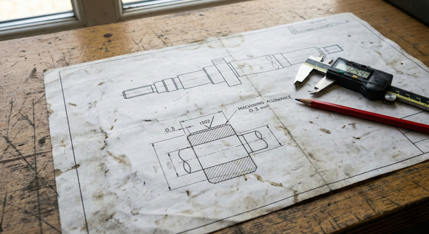
- ISO Symbology: Utilizing the ISO 1302 surface texture symbol is the standard method. Placing a machining allowance value (in millimeters) to the left of the surface texture symbol (e.g., “3 mm”) explicitly tells the manufacturer how much material to leave for that specific surface.
- CAD Modeling: In complex CAM workflows, the best practice is to model the finished part (Net Shape) and allow the CAM engineer to define the “Stock Body” or “Near Net Shape” in the software. However, if you are providing a casting model, ensure the raw casting model and the finished machine model are separate configurations.
At APT, we review every design for manufacturability (DFM). By optimizing your machining allowance, we ensure that your parts are not only precise but are manufactured with the highest efficiency.
Do you have a project requiring tight tolerances and complex finishing? Contact the APT engineering team today to review your specifications and ensure your production runs smoothly from the first roughing pass to the final inspection.