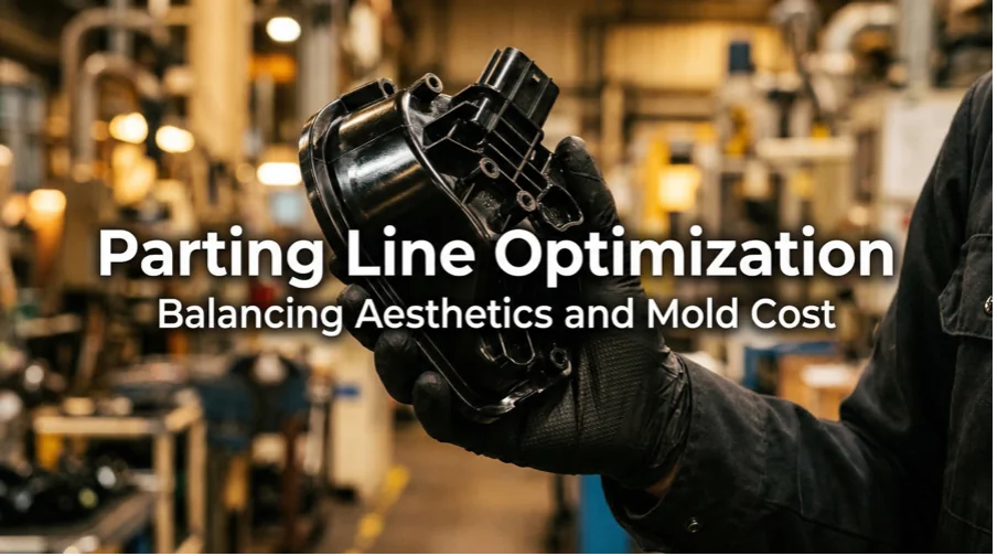
Every injection-molded part carries a parting line — the visible seam where the two halves of the mold meet and separate. While it is technically unavoidable, where that line sits and how it is shaped can make or break a product’s appearance, mold longevity, and overall tooling budget. In practice, parting line design is one of the earliest and most consequential decisions in mold engineering, yet it is frequently treated as an afterthought.
This article explains what a parting line really does beyond simply splitting the mold, examines how different parting line geometries influence cost, and shares practical techniques to minimize parting lines or hide them on finished parts. Whether you are a product engineer refining a CAD model or a procurement lead evaluating tooling quotes, understanding these trade-offs will help you make smarter design and sourcing decisions.
What a Parting Line Really Does
At its simplest, the parting line marks the boundary between the core and cavity halves of an injection mold. When the mold closes, molten plastic fills the space formed between these halves; when it opens, the part is ejected along that boundary. But the parting line’s role extends well beyond mold separation.
Primary venting path.
As plastic enters the cavity, it displaces the air already inside. That air must escape, and the parting line is the most common and effective exhaust route. Vents machined along the parting surface — typically shallow channels only 0.012 to 0.05 mm deep — allow air to exit without letting plastic leak through. If the parting line is poorly positioned relative to the melt-flow path, trapped air can compress and ignite under the combined effect of pressure and heat — a phenomenon known as the “diesel effect” — causing burn marks on the part and accelerated wear on the mold steel.
Flash-prone zone.
Flash — the thin film of excess plastic that bleeds out between mold halves — forms most readily along the parting line. Even a minor mismatch in clamping force or a slight surface imperfection at the parting surface can produce visible flash that requires secondary trimming, adding cost and cycle time. Because both venting and flash control depend on parting line geometry, the decision of where and how to draw that line directly shapes part quality, mold maintenance schedules, and production efficiency.
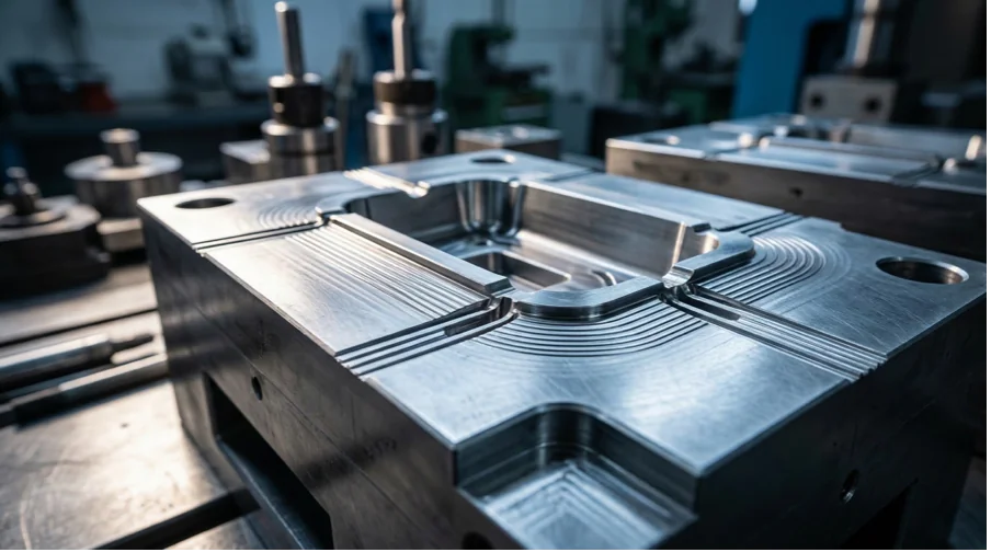
How Parting Line Geometry Affects Mold Cost
Not all parting lines are created equal. The geometry you choose influences CNC machining complexity, mold fitting time, and long-term maintenance — all of which feed into tooling cost. Three common types are worth comparing.
Flat (straight) parting line.
This is the simplest configuration: a single plane perpendicular to the mold opening direction. Because the parting surface is flat, it can be machined quickly on a standard CNC mill, and the two halves seal evenly with minimal fitting. For straightforward geometries like flat panels or rectangular enclosures, a flat parting line keeps tooling costs at their lowest.
Stepped parting line.
When a part has features at different heights, the parting surface may need to follow multiple planes, creating a stair-step profile. Each step adds machining passes, increases fitting difficulty, and introduces an uneven clamping force distribution that can lead to flash on the shallower side if not carefully managed. A common countermeasure is to arrange cavities symmetrically to balance injection force, but this adds engineering time and may increase mold size.
Curved (contoured) parting line.
For parts with organic or complex exterior shapes — think automotive interior panels or consumer electronics housings — the parting line often needs to follow a three-dimensional contour. Machining a curved parting surface typically requires multi-axis CNC work and more extensive hand-fitting to achieve a tight seal. The result is significantly higher tooling cost compared to a flat parting line, but it is sometimes the only option if the design demands a seamless appearance on all visible surfaces.
In general, the more complex the parting line geometry, the higher the mold price. When evaluating tooling quotes, understanding which type of parting line your part requires — and whether design modifications could simplify it — is one of the most direct levers for controlling factors affecting mold cost.
Practical Design Tricks to Minimize Visible Parting Lines
Since parting lines cannot be eliminated entirely, the next best strategy is to make them invisible — or at least inconspicuous — on the finished product. The following techniques are widely used by experienced mold designers to minimize parting lines on cosmetic surfaces.
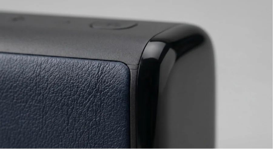
Place the parting line on a sharp edge or corner.
The human eye naturally expects a transition at a sharp geometric boundary. By routing the parting line along an existing edge or corner of the part, any residual witness mark blends into the geometry and becomes nearly undetectable. This is often the single most effective way to hide a parting line without adding tooling complexity.
Use radii to soften the transition.
When a parting line must cross a visible surface and cannot sit on a sharp edge, introducing a small radius at the parting boundary helps the seam blend with the surrounding geometry. The fillet radius diffuses light reflections across the transition, making the witness line less prominent compared to a hard, flat joint.
Align the parting line with a texture boundary.
Many injection-molded parts feature surface textures such as leather grain, sand blast, or geometric patterns. If the parting line is positioned at the boundary where a textured zone meets a smooth zone — or where two different textures meet — the visual “noise” of the texture naturally masks the seam. This is a particularly popular approach for automotive interior trim and consumer electronics casings.
Consider gate and ejector pin placement together.
Parting line location also constrains where gates and ejector pins can be placed. A gate that feeds against the parting line can cause jetting or weld-line issues, while ejector pins positioned too close to the parting surface may leave marks on cosmetic faces. Optimizing all three elements together — parting line, gate location, and ejection strategy — during early design stages avoids costly rework later.
Confirm Parting Line Location During DFM
Too often, parting line placement is treated as a mold-shop decision rather than a design-stage conversation. By the time a tooling engineer flags a problematic parting line, the product design may already be locked, leaving limited room for adjustment. The result is either a compromised cosmetic surface or an expensive mold revision.
This is why Design for Manufacturability (DFM) review should explicitly address parting line position as one of its early checkpoints. A thorough DFM discussion between the product designer and the mold maker should cover the direction of mold opening (line of draw) and how it determines parting line location; which surfaces are cosmetic or functional and must remain free of witness marks; how the parting line geometry affects venting strategy and flash risk; and whether simplifying the parting line — even with minor design adjustments — can reduce tooling cost without compromising function.
At APT-Mold, every injection molding project begins with a comprehensive DFM review. Our engineering team evaluates parting line options alongside draft angles, wall thickness, gate placement, and ejection strategy to identify the best balance of part quality, appearance, and mold cost before a single block of steel is cut. This upfront collaboration has helped clients across automotive, medical, and consumer product sectors avoid late-stage surprises and reduce overall development timelines.
Conclusion
Parting line optimization is not a cosmetic afterthought — it is a structural decision that influences mold cost, part quality, venting performance, and production efficiency. A flat parting line keeps tooling affordable; a contoured one may be necessary for complex aesthetics but comes at a premium. Design tricks like edge placement, radii transitions, and texture-boundary alignment can dramatically reduce visible seams on finished parts.
The key is to start the conversation early. By addressing parting line design during DFM — before mold steel is ordered — you create room to balance aesthetics and budget without compromise.
Need help optimizing your parting line strategy? Contact APT-Mold’s engineering team for a free DFM review. Upload your CAD files and project details, and we’ll provide a detailed quotation with parting line recommendations within 24 hours.