Polyether ether ketone (PEEK) is a high-performance semi-crystalline thermoplastic widely utilized in production. From aerospace brackets and semiconductor components to medical devices and industrial seals, manufacturers rely on PEEK when long-term reliability is required.

Choosing the correct production method directly impacts the dimensional accuracy, mechanical performance, and total cost of the component. A process that works well for a prototype may become unnecessarily expensive for mass production, while a method designed for high-volume manufacturing may not deliver the flexibility needed for prototype testing.
This guide analyzes the structural properties of PEEK and compares computer numerical control systems (CNC machining), injection molding, and 3D printing to assist in manufacturing selection.
What Makes PEEK Different from Other Engineering Plastics?
PEEK stands out because it maintains its mechanical properties under conditions that exceed the limits of most engineering plastics.
High Temperature Resistance
PEEK maintains its mechanical properties at temperatures that exceed the operating range of most engineering plastics. According to Victrex, it has a melting point of approximately 343°C and an operating temperature of up to 260°C. These characteristics make it suitable for components exposed to prolonged heat.
Chemical Resistance
The material offers high chemical resistance, enduring exposure to hydraulic fluids, solvents, and acids at elevated temperatures. Its low coefficient of friction and high wear resistance make it suitable for oil and gas components, aerospace fasteners, and automotive transmission systems.
Biocompatibility
In medical applications, certain medical-grade PEEK materials are widely used in implantable and medical applications because of their biocompatibility and mechanical performance. The material withstands repeated autoclaving cycles without dimensional degradation or hydrolytic breakdown.
PEEK is widely used as a functional replacement for metal because it combines a high strength-to-weight ratio with excellent chemical resistance, electrical insulation, and dimensional stability. It also retains reliable mechanical properties at continuous operating temperatures of up to 260°C, enabling long-term use in high-temperature, high-pressure, and corrosive environments where metals have traditionally been used.
What are the Main Challenges When Manufacturing PEEK via CNC Machining?
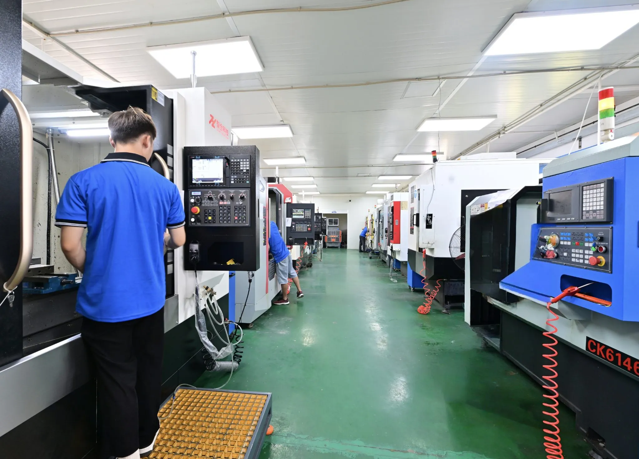
Manufacturing PEEK via CNC machining requires precise thermal management because the material has a low thermal conductivity, which concentrates friction heat at the cutting zone. Without specific parameters, this heat accumulation causes localized melting, dimensional distortion, and high internal stresses.
To prevent internal stress cracking and ensure structural stability, raw PEEK blanks must undergo a controlled stress-relief annealing process before and between machining stages. Heating the material slowly above its glass transition temperature of 143°C and cooling it at a rate of 10°C per hour until the system falls below 140°C prevents subsequent warping during material removal.
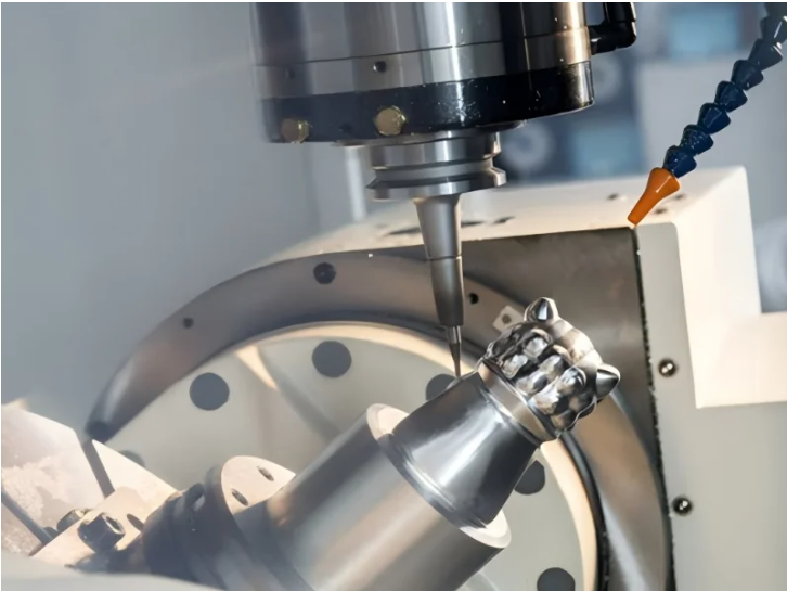
Tool wear also represents an additional challenge due to the mechanical strength of the polymer, especially when processing carbon-fiber-reinforced or glass-fiber-reinforced grades. Standard high-speed steel tools dull rapidly, necessitating solid carbide or diamond-coated tooling to maintain tight tolerances.
What Are the Technical Challenges When Injection Molding PEEK?
Injection molding PEEK requires specialized high-temperature processing equipment because the material requires a melt temperature between 360°C and 400°C to achieve proper flow characteristics. Standard molding presses cannot maintain these profiles, requiring ceramic heater bands and heavy-duty barrel insulation.
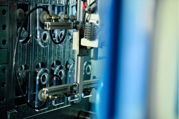
Mold temperature control is critical to managing the crystallinity of the molded part, requiring specialized oil or cartridge heating systems capable of holding mold temperatures between 160°C and 190°C. If the mold temperature drops below 150°C. The PEEK material cools too quickly, resulting in an amorphous, brittle outer shell with poor mechanical properties.
High volumetric shrinkage rates ranging from 1.0% to 2.5% require precise gate positioning and runner designs to prevent sink marks, voids, and internal knit lines. The high viscosity of molten PEEK also demands high injection pressures and fast injection speeds, which accelerates mold cavity wear and requires hardened tool steels like H13.
When Should You Consider 3D Printing PEEK Components?
PEEK 3D printing using Fused Deposition Modeling (FDM) or Selective Laser Sintering (SLS) allows for the production of complex lattice structures that are mathematically impossible to form using CNC machining or injection molding. This process builds parts layer-by-layer without requiring custom tooling, reducing upfront capital requirements for low-volume production runs.
Additive manufacturing provides a distinct advantage when producing parts with geometric complexities that are inaccessible to subtractive CNC cutting paths or traditional injection molding draft angles.
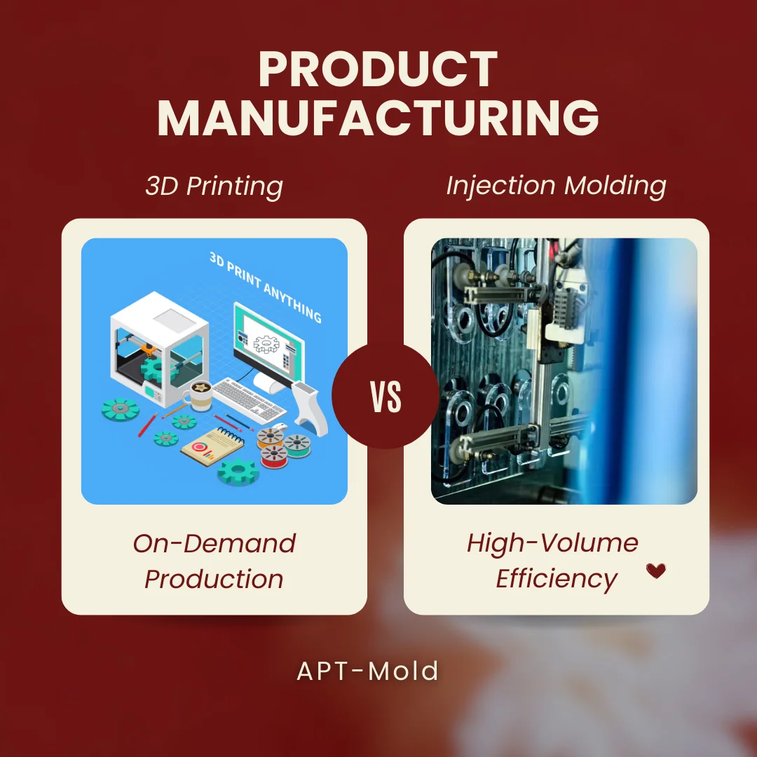
PEEK 3D printing allows engineers to design organic topologies, internal fluid channels, and lightweight lattice structures. These lattice geometries reduce component weight while preserving mechanical rigidity, a characteristic required for aerospace brackets and orthopedic implants where bone ingrowth into the porous structure is desired.
Because 3D printing requires no physical molds, tooling, or custom fixtures, the setup cost is minimal. This makes the technology efficient for rapid prototyping, fit-testing, and low-volume production runs. A designer can modify a Digital Computer-Aided Design (CAD) file and initiate a print immediately, bypassing the several weeks’ lead time associated with cutting steel injection mold cores.
However, printed PEEK parts exhibit anisotropic mechanical properties. The tensile strength perpendicular to the print bed (Z-axis) is typically 20% to 30% lower than the strength parallel to the extrusion layers (X-Y plane) due to intermolecular bonding limitations between layers. Environmental control within the print chamber is critical; the ambient build-chamber temperature must exceed 180°C to manage cooling rates and facilitate layer adhesion, preventing part warping and delamination during the build process.
Which PEEK Manufacturing Process Fits Your Project Requirements?
Selecting the correct PEEK manufacturing process requires balancing production volume, geometric complexity, and the required dimensional tolerances. CNC machining delivers the highest dimensional accuracy for low-to-medium volumes, injection molding provides the lowest unit cost at high volumes, and 3D printing supports highly customized or complex geometries.
| Manufacturing Metric | CNC Machining | Injection Molding | 3D Printing (FDM / SLS) |
| Standard Tolerances | ±0.025 mm to ±0.05 mm | ±0.05 mm to ±0.1 mm | ±0.1 mm to ±0.2 mm |
| Economical Production | 1 to 500 units | 1,000+ units | 1 to 50 units |
| Tooling Cost & Lead Time | $0 (No custom tooling) | High ($5,000-$20,000+), 4-6 weeks | $0 (No custom tooling) |
| Geometric Capabilities | Limited by tool access and line-of-sight | Limited by draft angles and uniform walls | Supports complex internal lattices |
| Material Efficiency | Low (Subtractive waste) | High (Minimal waste, reusable runners) | High (Additive, low material waste) |
| Mechanical Integrity | Isotropic (Uniform high strength) | Isotropic (High structural strength) | Anisotropic (Weaker Z- axis bonding) |
For applications requiring strict dimensional tolerances below ±0.05 mm or production runs under 500 pieces, CNC machining remains the most reliable option. When production moves to scale beyond 1,000 parts, the high initial tooling investment of injection molding is offset by the low cycle times and reduced per-part cost. For highly customized, low-volume parts with complex internal cavities, 3D printing serves as the optimal production method.
At APT Mold, we help customers evaluate these trade-offs during the early design stage, considering production quantity and performance requirements before selecting the most appropriate process. By matching the manufacturing method to the application, engineering teams can reduce development risks, control production costs, and improve long-term product performance.